- 您现在的位置:买卖IC网 > Sheet目录960 > AQV257MAZ (Panasonic Electric Works)RELAY OPTO AC/DC 200V 250MA 6SMD
�� ��
��
��HE� 1� Form� A� (AQV25� ?� )�
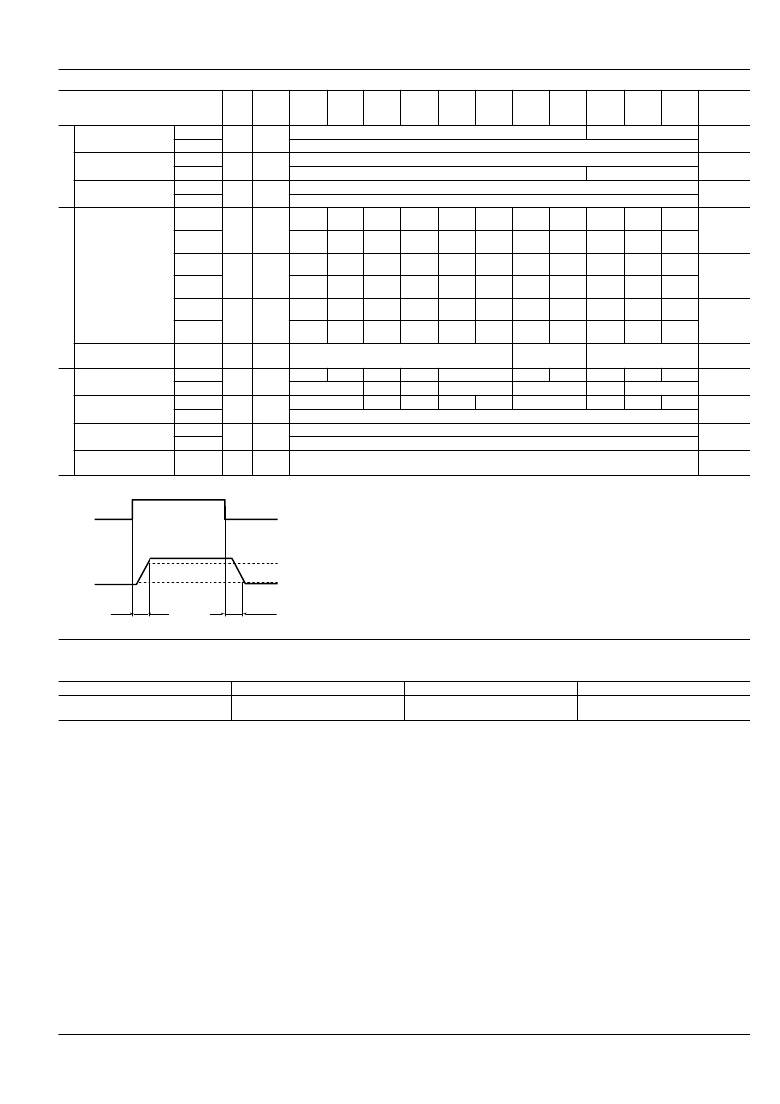
�2.� Electrical� characteristics� (Ambient� temperature:� 25� °� C� 77� °� F� )�
�Item�
�Sym-�
�bol�
�Type� of�
�con-�
�nection�
�AQV251(A)� AQV252(A)� AQV255(A)� AQV257(A)� AQV253(A)� AQV254(A)� AQV259(A)� AQV258(A)� AQV253H(A)� AQV254H(A)� AQV256H(A)� Condition�
�LED� operate� current�
�LED� turn� off� current�
�LED� dropout� voltage�
�Typical�
�Maximum�
�Minimum�
�Typical�
�Typical�
�Maximum�
�I� Fon�
�I� Foff�
�V� F�
�—�
�—�
�—�
�0.9� mA� 1.4� mA�
�3� mA�
�0.4� mA�
�0.8� mA� 1.3� mA�
�1.25� V� (1.14� V� at� I� F� =� 5� mA)�
�1.5� V�
�I� L� =� Max.�
�I� L� =� Max.�
�I� F� =� 50� mA�
�Typical�
�Maximum�
�R� on�
�A�
�0.6� ?�
�1� ?�
�0.74� ?�
�1.4� ?�
�1.8� ?�
�2.5� ?�
�2.6� ?�
�4� ?�
�5.5� ?�
�8� ?�
�12.4� ?�
�16� ?�
�85� ?�
�200� ?�
�345� ?�
�500� ?�
�5.5� ?�
�8� ?�
�12.4� ?�
�16� ?�
�20� ?�
�30� ?�
�I� F� =� 5� mA�
�I� L� =� Max.�
�Within� 1� s�
�on� time�
�On� resistance�
�Typical�
�Maximum�
�Typical�
�Maximum�
�R� on�
�R� on�
�B�
�C�
�0.3� ?�
�0.5� ?�
�0.15� ?�
�0.25� ?�
�0.37� ?�
�0.7� ?�
�0.18� ?�
�0.35� ?�
�0.9� ?�
�1.25� ?�
�0.45� ?�
�0.63� ?�
�1.4� ?�
�2� ?�
�0.7� ?�
�1� ?�
�2.7� ?�
�4� ?�
�1.4� ?�
�2� ?�
�6.2� ?�
�8� ?�
�3.1� ?�
�4� ?�
�60� ?�
�100� ?�
�30� ?�
�50� ?�
�345� ?�
�500� ?�
�160� ?�
�250� ?�
�2.7� ?�
�4� ?�
�1.4� ?�
�2� ?�
�6.2� ?�
�8� ?�
�3.1� ?�
�4� ?�
�15� ?�
�20� ?�
�7.5� ?�
�10� ?�
�I� F� =� 5� mA�
�I� L� =� Max.�
�Within� 1� s�
�on� time�
�I� F� =� 5� mA�
�I� L� =� Max.�
�Within� 1� s�
�on� time�
�Off� state� leakage�
�current�
�Maximum�
�I� Leak�
�—� 1� μ� A� 10� μ� A� 1� μ� A�
�I� F� =� 0� mA�
�V� L� =� Max.�
�Turn� on� time*�
�Typical�
�Maximum�
�T� on�
�—�
�1.7� ms� 1.4� ms� 0.9� ms� 1.5� ms� 0.8� ms� 0.6� ms� 0.35� ms� 2.4� ms� 1.8� ms� 1.2� ms� I� F� =� 5� mA�
�3� ms� 2� ms� 3� ms� 2� ms� 1� ms� 4� ms� 3ms� I� L� =� Max.�
�Turn� off� time*�
�I/O� capacitance�
�Initial� I/O� isolation�
�resistance�
�Typical�
�Maximum�
�Typical�
�Maximum�
�Minimum�
�T� off�
�C� iso�
�R� iso�
�—�
�—�
�—�
�0.07� ms�
�0.09� ms� 0.1� ms� 0.06� ms� 0.05� ms�
�0.2� ms�
�1.3� pF�
�3� pF�
�1,000� M� ?�
�0.04� ms�
�0.06� ms� 0.05� ms� 0.06� ms� I� F� =� 5� mA�
�I� L� =� Max.�
�f� =� 1� MHz�
�V� B� =� 0� V�
�500� V� DC�
�*Turn� on/Turn� off� time�
�Input�
�90%�
�Output�
�Ton�
�Toff�
�10%�
�RECOMMENDED� OPERATING� CONDITIONS�
�Please� obey� the� following� conditions� to� ensure� proper� device� operation� and� resetting.�
�Item�
�Input� LED� current�
�Symbol�
�I� F�
�Recommended� value�
�Standard� type:� 5�
�Reinforced� insulation� type:� 5� to� 10�
�Unit�
�mA�
�■� For� Dimensions.�
�■� For� Schematic� and� Wiring� Diagrams.�
�■� For� Cautions� for� Use.�
�■� These� products� are� not� designed� for� automotive� use.�
�If� you� are� considering� to� use� these� products� for� automotive� applications,� please� contact� your� local� Panasonic� Corporation�
�technical� representative.�
�For� more� information.�
�■� Continual� DC� bias� (for� AQV258� ??� ,� AQV259� ??� )�
�In� cases� in� which� a� continual� DC� bias� is� applied� between� the� input� and� output,� the� output-side� MOS-FET� may� deteriorate�
�due� to� the� voltage.� Therefore,� please� verify� operation� of� the� actual� design� before� using.� An� example� of� a� circuit� that� might�
�undergo� MOS-FET� deterioration� due� to� voltage� is� given� below.�
�ASCTB143E� 201201-T�
�Panasonic� Corporation�
�Automation� Controls� Business� Unit�
�industrial.panasonic.com/ac/e�
�发布紧急采购,3分钟左右您将得到回复。
相关PDF资料
AQV414EHA
RELAY OPTO SPST-NC 120MA 6-SMD
AQV414H
RELAY OPTO AC/DC 400V 120MA 6DIP
AQV414SX
RELAY OPTO AC/DC 400V 100MA 6SOP
AQW210HLA
RELAY OPTO DPST-NO 120MA 8 SMD
AQW216EH
RELAY SSR DPST-NO 40MA 600V 8DIP
AQW217
RELAY OPTO AC/DC 200V 160MA 8DIP
AQW223R2S
RELAY SSR DPST 140MA 250V 8SOP
AQW254AX
RELAY OPTO AC/DC 400V 120MA 8SMD
相关代理商/技术参数
AQV257X
制造商:Panasonic Electric Works 功能描述:
AQV258
功能描述:固态继电器-PCB安装 20MA 1500V SPST
RoHS:否 制造商:Omron Electronics 控制电压范围: 负载电压额定值:40 V 负载电流额定值:120 mA 触点形式:1 Form A (SPST-NO) 输出设备:MOSFET 封装 / 箱体:USOP-4 安装风格:SMD/SMT
AQV258A
功能描述:固态继电器-PCB安装 20MA 1500V 6PIN SPST RoHS:否 制造商:Omron Electronics 控制电压范围: 负载电压额定值:40 V 负载电流额定值:120 mA 触点形式:1 Form A (SPST-NO) 输出设备:MOSFET 封装 / 箱体:USOP-4 安装风格:SMD/SMT
AQV-258A
制造商:Panasonic 功能描述:Bulk 制造商:Panasonic 功能描述:Relay SSR 50mA 1.5V DC-IN 0.02A 1500V AC/DC-OUT 6-Pin PDIP SMD Tube
AQV258AJ
制造商:Panasonic Electric Works 功能描述:
AQV258AX
功能描述:固态继电器-PCB安装 1500V 20MA 6-SMD Relay OPTO RoHS:否 制造商:Omron Electronics 控制电压范围: 负载电压额定值:40 V 负载电流额定值:120 mA 触点形式:1 Form A (SPST-NO) 输出设备:MOSFET 封装 / 箱体:USOP-4 安装风格:SMD/SMT
AQV258AZ
功能描述:固态继电器-PCB安装 1500v 20mA DIP Form A Norm-Open RoHS:否 制造商:Omron Electronics 控制电压范围: 负载电压额定值:40 V 负载电流额定值:120 mA 触点形式:1 Form A (SPST-NO) 输出设备:MOSFET 封装 / 箱体:USOP-4 安装风格:SMD/SMT
AQV258AZJ
制造商:Panasonic Electric Works 功能描述: